Ionosonde
An ionosonde is a radar system looking vertically upwards. With it, the density of free electrons in the ionosphere can be observed as a function of the height.
The ionosonde transmits radio waves upwards, which are reflected by free electrons in the ionosphere, and subsequently received on the ground. The reflection occurs at the height at which the plasma frequency is equal to the frequency of the radio wave.
From the time it takes for the reflected signals to return, the reflection height can be derived. The electron density at the reflection point can also be calculated: there is a direct relationship between the plasma frequency and the electron density.
The ionosonde varies its transmission frequency in regular sweeps, for example from 0.5 MHz to 20 MHz. At each frequency a different reflection height is recorded. When the frequency of the ionosonde exceeds the highest plasma frequency in the ionosphere, the radio waves will pierce the ionosphere and the signal is no longer received.

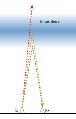
Figure 1: Working principle of an ionosonde. Signals of different frequencies are reflected at different altitudes, or escape into space. Tx = transmitter, Rx = receiver.
This is shown in Figure 1. The lowest frequency — shown in green — is reflected at the bottom of the ionosphere, where the electron density is low. A higher frequency — shown in orange — is reflected at the height where the maximum electron density occurs. This is called the critical frequency. Radio waves with frequencies that are higher than the critical frequency — such as the one shown here in red — are not reflected and escape into space.
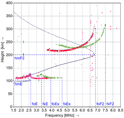
The frequencies and their associated reflection heights can be plotted in an ionogram, from which several important ionospheric parameters can be derived. Figure 2 shows an example of such an ionogram. The red and green traces show the ionospheric reflection. The ionosphere is a bi-refractive medium, each upward wave results in two reflections, the ordinary (shown in red) and extraordinary (shown in green) wave. The black line is drawn by a computer program, and shows the plasma frequency as a function of the true height. This is slightly lower than the height shown by the traces, as corrections are needed for slightly lower speed of the radio waves in the ionosphere, as compared to the speed of light in vacuum.
The blue lines show automatically determined parameters of the ionosphere: hmF2 is the height at which the maximum electron density of the occurs. This region is called the ‘F2-region’. hmE is the height of a local maximum in the ‘E-region’. foF2 and fxF2 are the critical frequencies of the F2-region for the ordinary and extraordinary wave. foE, fxE, foEs, and fxEs are the same for the normal and sporadic E-region reflections.
It can be seen that at hmF2 occurs at a certain height, after which the electron density decreases again. The ionosonde can only measure up to this maximum. Different instruments are needed to measure the topside of the ionosphere. The dashed black line that shows the topside of the ionosphere is not measured by the ionosonde, but calculated from a model.

Figure 2: Example of an ionogram, recorded by the ionosonde at Dourbes, Belgium, on 2021-12-17 at 11:05 UTC. Explanation: see text.(Credits: PITHIA-NRF/Tobias Verhulst/Ben Witvliet)
The ionosphere is not static, it varies over time. The ionosonde will try to capture these variations with repeated frequency sweeps. Typical repetition time is between five and fifteen minutes.
The ionosphere is also different above different geographical locations, and one ionosonde can only ‘see’ the ionosphere directly above its location. Therefore, multiple ionosondes are needed to get a complete picture of the ionosphere over a wider area. Data from several observatories are combined to produce real-time maps of the ionosphere above Europe.
Various types of ionosonde are in operation throughout Europe and the world. These include the AIS-INGV system, the Digisonde DPS4D, and the Dynasonde. Although these systems are different in hardware and software implementation, their main operating principle is the same.
 |
 |
|
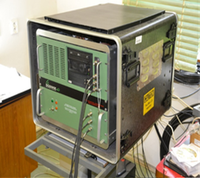
Figure 3: Ionosonde instrument of the Průhonice observatory. |
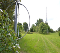
Figure 4: Ionosonde antennas of the Průhonice observatory. Background: transmit antenna tower, front: receive antenna. |
For questions, please contact outreach@pithia-nrf.eu
