Continuous Doppler Sounding System
The Continuous Doppler Sounding System consists of one or more transmitters and a receiver. The transmitters send a continuous radio wave of a fixed frequency to the ionosphere, which is then reflected, after which the receiver measures the Doppler shift of the reflected wave. The Doppler shift results from the motion of reflecting level or from the changes of electron density.
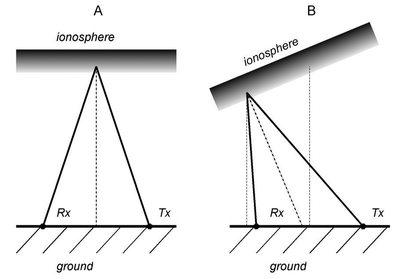
The operating principle is depicted in Figure 1. The reflection point between the transmitter and receiver lies in the midpoint if horizontal gradients of electron density are absent (A). Horizontal gradients of electron density in the ionosphere will cause a shift of the reflection point from the midpoint towards the transmitter or receiver (B). The reflection height depends on the electron density in the ionosphere and can be determined using a nearby ionosonde.

Figure 1: A sketch of the radio waves emitted by the transmitter (Tx), reflected by the ionosphere and captured by the receiver (Rx).
When multiple transmitters or receivers are installed to create a multi-point Continuous Doppler Sounding System, it becomes possible to investigate the propagation of atmospheric waves and other disturbances in the ionosphere. These disturbances may be caused by solar flares, the solar terminator, geomagnetic activity, strong tropospheric convection, strong seismic events, human-made explosions etc. The advantage of this system is its high time resolution. The Continuous Doppler Sounding System can detect ionospheric fluctuations with periods of 10 seconds and larger and is most suitable for studying waves of periods from 20 seconds to 100 minutes.
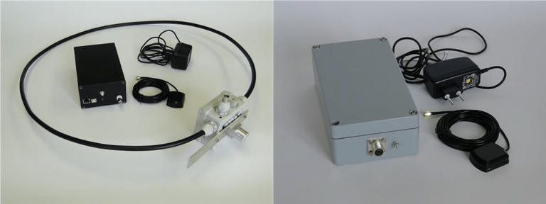
The Continuous Doppler Sounding System developed by IAP (a consortium partner in the PITHIA-NRF project) are operated in collaboration with international partners, in the Czech Republic, northern Argentina, Taiwan, and South Africa, with a future system planned in Belgium. This instrument operates at fixed frequencies between 3.5 and 7 MHz, which can be selected depending on the local ionospheric conditions. The transmitted power is 1 Watt. Only a continuous wave is transmitted, with a periodic identification using on/off keying. GPS is used for the synchronisation of the transmitters and receiver.

Figure 2: The CDSS receiver set (on the left) and the transmitter set (on the right)
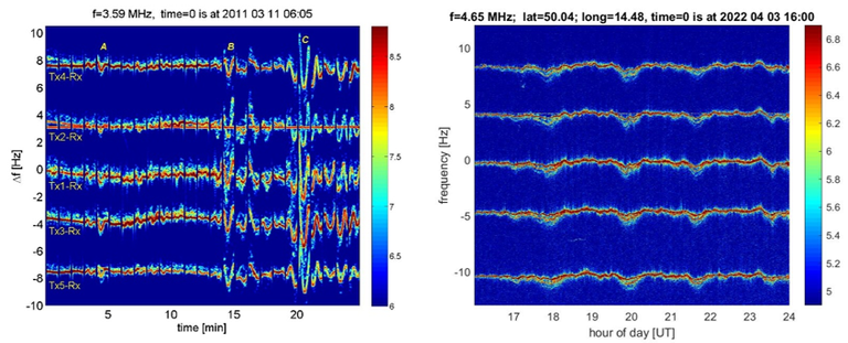
Our instruments use at least three different transmitters, with the various transmitters installed around a single, central receiver. The distance from the receiver to each transmitter is around 100 km. The frequencies of the individual transmitters are shifted by 4 Hz so that the signals of all transmitters can be displayed in one Doppler shift spectrogram (Figure 3). All the oscillators in the transmitters and receivers are very stable (frequency drift in the order of 10-10) to allow detection of small Doppler shifts.
Figure 3 shows a Doppler shift spectrogram recorded during the Japanese earthquake of 11 March 2011 (on the left). The earthquake occurred below the North Pacific Ocean, 130 km east of Sendai, the largest city in the Tohoku region, a northern part of the Honshu island. The magnitude 9.0 earthquake struck at 2:46 PM. The left spectrogram shows the signals of five transmitters received by a single receiver at the Panska Ves observatory in the Czech Republic. The disturbance caused by the earthquake can clearly be observed. The right spectrogram shows the resulting gravity waves, observed at the same observatory.

Figure 3: Doppler shift spectrogram recorded during the Japanese earthquake of 11 March 2011 (left). Observation of gravity waves at the same observatory (right). Signals are obtained from five transmitters.
